
A speed reading without a plate cannot become a challan. A plate without a trustworthy speed reading cannot either. This post explains how the two sensors are combined, with the maths behind each source of error. Numbers marked as assumptions are for illustration and are not product specifications.
Key points
- Doppler radar measures the speed component along the radar's line of sight. The angle to the vehicle's path makes the reading lower, never higher.
- A 4D radar adds position (range, azimuth, elevation) to speed, so each reading can be placed on the road.
- Calibration maps radar coordinates to image pixels, so a radar track lands on the right vehicle in the frame.
- Clock alignment matters: at 230 km/h, a 10 ms timing error moves the vehicle 0.64 m.
- Section speed uses two gantries and a shared clock; a 1 s timing error over 10 km at 120 km/h changes the result by about 0.4 km/h.
What the radar measures
A Doppler radar sends a signal and measures the frequency shift of the reflection. The shift is proportional to the speed component along the radar's line of sight:
f_d = 2 x v x f_0 x cos(theta) / c

f_d   = Doppler shift (Hz)
v     = vehicle speed (m/s)
f_0   = radar carrier frequency (Hz)
theta = angle between the radar beam and the direction of travel
c     = speed of light, 299,792,458 m/s
Worked example, with a 24.125 GHz carrier as an assumption: a vehicle at 100 km/h (27.78 m/s) moving straight along the beam gives a shift of about 4,470 Hz.
The radar recovers v cos(theta). If the angle is not corrected, the reading is low by a factor of cos(theta):
| Angle | Reading low by |
|---|---|
| 5° | 0.38% |
| 10° | 1.52% |
| 20° | 6.03% |
An uncorrected cosine error always favours the driver. A tracking radar that knows each vehicle's position can correct for the angle, which makes the installation geometry part of the measurement. OIML R 91 is the international recommendation for radar equipment that measures vehicle speed.
Why a 4D radar
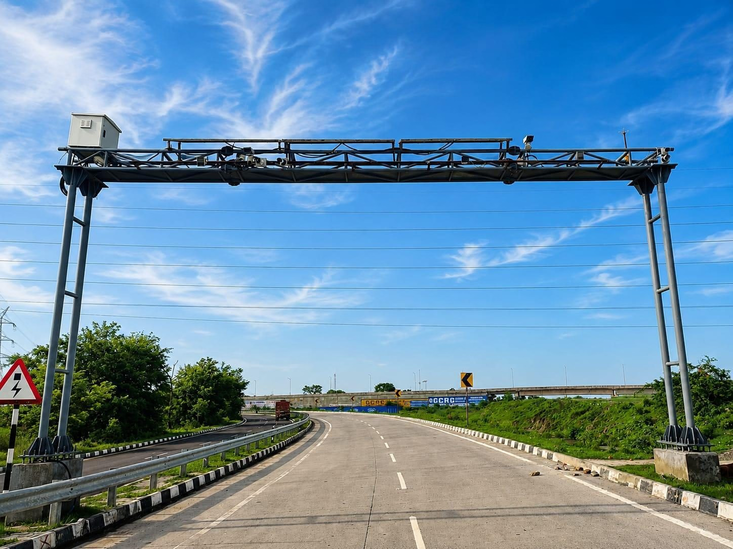
A simple radar gives a speed and a signal strength. It cannot say which of several vehicles produced the reading. A 4D radar reports range, horizontal angle, vertical angle and radial speed for each target, so it can track many vehicles at once and place each one on the road. The radar in our VSDS tracks up to 128 vehicles simultaneously across multiple lanes, and the VSDS covers up to 60 m of detection range across the capture zone.
Fusion: one track, one vehicle, one plate
The fusion step answers one question for every radar track: which vehicle in the image is this? A typical pipeline has four stages:
- Time alignment: radar readings and camera frames carry timestamps from a shared clock. Each radar position is interpolated to the frame time.
- Projection: the radar position on the road plane is mapped into image pixels with a calibration transform.
- Association: the projected point is matched to the nearest vehicle detection, inside a gate that rejects matches that are too far away.
- Evidence: the matched detection's plate read, class and lane are attached to the speed reading.
Timing error turns directly into position error:
position error (m) = speed (m/s) x timing error (s)
at 230 km/h, 10 ms -> 63.9 m/s x 0.010 s = 0.64 m
In dense traffic, gaps between vehicles can be a few metres, so a timing error of tens of milliseconds can push the projected point onto the wrong vehicle. That is why the gate size, the clock and the frame rate have to be designed together. The Recon camera captures at 60 FPS, so frames are 16.7 ms apart.
Calibration
Calibration is the work that makes projection correct. In general it covers:
- Mounting geometry: height, tilt and position of both sensors on the gantry, measured at installation.
- Radar alignment: the radar's axis relative to the lanes, which sets the angle correction.
- Camera to road: a mapping from image pixels to positions on the road plane, fitted from known marks such as lane lines.
- Radar to camera: the transform that places radar targets on the camera's road plane.
- Lane map: lane boundaries in both coordinate systems, so each reading carries a lane ID.
- Field check: passes with a reference vehicle whose speed is known from an independent source, compared with the system's readings.
A gantry moves with wind and temperature, and mounts can shift over time. Calibration is therefore checked again during maintenance, not only at installation.
Spot speed and section speed
Spot speed is measured at one gantry. Section speed is average speed between two gantries. In the NHAI 2023 circular, VIDES gantries are typically 10 km apart, and section speed is calculated from the travel time between them.
average speed = distance / (time at gantry B - time at gantry A)
10 km in 300 s            = 120.0 km/h
10 km in 299 s (1 s error) = 120.4 km/h
Section speed depends on correct plate matching at both gantries and on clocks that agree. It also catches drivers who slow down only at the camera.
What the evidence contains
Each VSDS violation produces a timestamped, geo-tagged evidence image showing the vehicle, the plate with OCR, the speed reading, the violation type and the lane position. The system supports separate speed limits per vehicle class, for example 80 km/h for commercial vehicles and 120 km/h for cars on the same stretch. Violations go to EdgeTrack for officer validation, and approved violations are pushed to NIC for e-challan.
The Recon Global Shutter Camera is NATRAX certified for radar-based speed detection up to 230 km/h and vision-based detection up to 180 km/h. See the VSDS page for the full system. Our global shutter post explains why the evidence image stays sharp at speed, and our accuracy post covers how to test the plate read. More briefs are on the Research page.
Frequently asked questions
Can a camera measure speed without radar?
Yes. A calibrated camera can measure the distance a vehicle moves between frames. Recon's NATRAX certification covers vision-based detection up to 180 km/h and radar-based detection up to 230 km/h.
What happens when two vehicles are side by side?
A 4D radar separates them by angle and range, and the lane map assigns each to its lane. The association gate then matches each track to the vehicle in that lane.
Does the cosine effect ever overstate speed?
No. cos(theta) is at most 1, so an uncorrected angle can only lower the reading.
Share this article